An accurate torque application in vehicle maintenance is crucial, as correct and incorrect torque levels can affect vehicle components. This article underscores the importance of using calibrated tools to follow manufacturers' specifications, preventing potential failures. Ideal, this guide demystifies torque settings, illustrating their impact on vehicle performance and longevity. It is a must-read for anyone passionate about maintaining their vehicle's integrity and optimizing its performance.
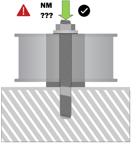
- FUNCTION OF THREADED FASTENERS: BOLTS – STUDS – NUTS:
Several types and sizes of threaded fasteners - fixings, are used within the automotive industry during the manufacturing processes of new vehicles and during service maintenance intervals – repairs.
Their function is to create a clamping force across the joint of the components, without loosening. A joint is designed to maintain the correct clamping force within set parameters for the operating environment conditions for the installation, i.e. (material type, temperature, loading, vibrations, frequencies).
Correctly torqued (tightened) fasteners make use of their materials elasticity properties. During the tightening process the fastener will stretch (extend), then it tries to return to its original length, (compresses) This process creates a compressive force across the joint components.
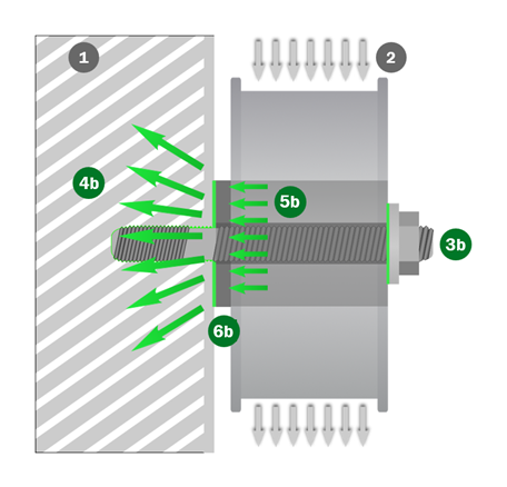
- The Pulley Is Mounted to The Engine Block. (1)
- With correct torque applied. (3b)
- Creating the correct clamping load. (4b)
- The load from the belt (2) transfers into the engine block and not just the shank of the fastener. (5b)
- Eliminating any shearing effect. (6b)
- THREADED FASTENERS - BOLTS - STUDS – NUTS: STRESS AND STRAIN.
The stress in a fastener is directly proportional to its strain. The stress-strain of a fastener will incorporate an elastic limit (elasticity) and a plastic limit (plasticity). During the tightening process the fastener will stretch (extend), within its elastic limit, and compress during the untightening process.
If a fastener is stressed beyond its proof load (maximum load capability within its elasticity limit) then the elastic range changes into plasticity range known as plastic deformation, therefore the strain is no longer proportional to stress. Once plastic deformation has occurred the fastener will not fully return or compress back to its original length after untightening.
The point which plastic deformation occurs is known as the (yield strength point). Further, tightening within the plastic deformation limit is where the fastener starts to fail, known as the ultimate tensile strength point (UTS). Once the UTS-point is reached, any additional tightening of the bolt causes further extension (stress), until fastener breakage occurs. The point where the fastener breaks is known as the (tensile point).
Stress And Strain Graph.

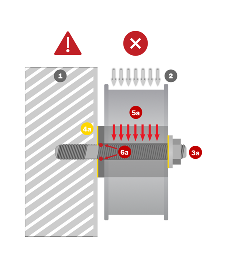
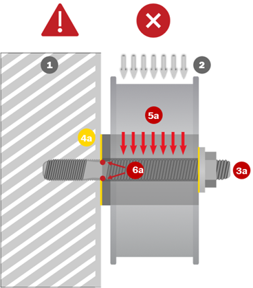
- INCORRECT INSUFFICIENT TORQUE: (TOO LOW).
- The Pulley Is Mounted to The Engine Block. (1)
- With incorrect torque applied (too low). (3a)
- Creating a low clamping load (4a) between the pulley mounting and the engine block.
- The load from the belt (2) is transferred directly onto the shank of the fastener. (5a)
- Creating a shearing effect causing the fastener to fail. (6a) (see Sheared Fastener)
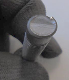
Incorrect Torque: (To Low). Sheared Fastener.
- INCORRECT EXCESSIVE TORQUE: (TO HIGH).
- The Pulley Is Mounted to The Engine Block. (1)
- With incorrect torque applied (too high) fastener stretches-extends past its elasticity limit, and enters the plasticity limit. (3a)
- Creating incorrect clamping load (4a) between the pulley mounting and the engine block.
- The load from the belt (2) is transferred directly onto the shank of the fastener. (5a) the stretched–extended section is a weak point which receives loads and various frequencies during engine operation.
- Eventually creating a shearing effect causing the fastener to fail. (6a)
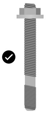
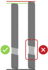
- Good condition fastener and a fastener that has been overtightened, past the elasticity limit, and has entered the plasticity limit, now it will not return to its original length. (see Fastener Condition).
Incorrect Torque: (To High). / Fastener Condition.
- INCORRECT CLAMPING LOAD: - (THREAD FAILURE).
If the vehicle manufacturers prescribed torque specifications and correct angular tightening process is not followed, the correct clamping force will not be achieved, and damage to the thread in the engine block may occur, some threaded, aluminium engine block applications are extremely sensitive to incorrect torque, vibrations, frequencies, and wear.
- The Pulley Is Mounted to The Engine Block. (1)
- If the thread fails (3a), the fasteners torque setting is lost, leading to incorrect clamping load (4a) between the pulley mounting and the engine block.
- The load from the belt (2) is transferred directly onto the shank of the fastener (5a) the stretched–extended section is a weak point which receives loads and various frequencies during engine operation.
- Eventually creating a shearing effect causing the fastener to fail. (6a)
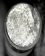
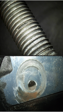
- Aluminium engine block thread failure, aluminium material in fastener thread, (see aluminium thread failure).
Incorrect Clamping Load: (Thread Failure). (Aluminium Thread Failure).

While tightening a nut/bolt, applying the prescribed torque value in Nm only, does not guarantee that the desired clamping force will be achieved; tests have shown that differences in clamping can occur.
Present-day instruction manuals recommend using a torque angle as well as a prescribed torque value (e.g., 20Nm + 45°).
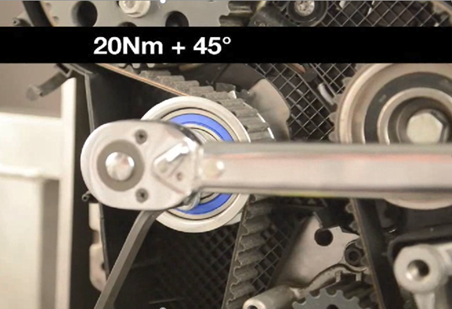
Using a torque angle enables a more accurate result. In some cases, the manual will instruct to 1st apply the prescribed torque, wait a while, then 2nd apply the angular torque, wait again, then 3rd apply angular torque again if required (and so on).
These required waiting periods are part of the tightening process to allow (settling or resting) time of the fixing, to ensure the correct amount of clamping force is achieved.
NOTE:
20Nm + 45° + 45°, Is different from 20Nm + 90°
Between the two 45° angular settings, the fastener is required to ‘settle’ or ‘rest’.

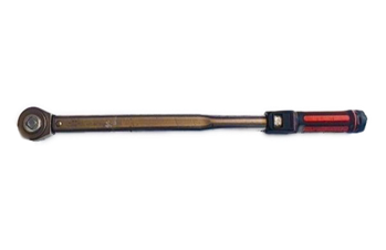
Gates recommends following the vehicle manufacturers torque specifications and that calibrated torque wrenches and torque angle setting tools are used for all critical fixing installations, to ensure the correct torque specifications are applied.